Rj12 Plug Wiring Diagram
Rj11 wiring diagram rj11 socket wiring diagram rj11 splitter wiring diagram rj11 wiring diagram every electric arrangement consists of various diverse parts. The tb standard is the most commonly used.
Rj45 To Rj12 Wiring Diagram RIAHSOSHI

15.08.2018 15.08.2018 6 comments on rj12 to rj11 wiring diagram in the usa it is called rj11 or rj14, depending on wiring configuration.

Rj12 plug wiring diagram. It also gives insights into how a usb works. Pin 8 → brown wire. Pin 7 → white and brown wire.
Using appropriate colors, the diagram labels all the wires in a usb cable and then informs what each color stands for. Rj11 12 110 type keystone jack connector telephone wiring reference free 90303wt white rj45 set 10pcs cat6 cat 3 utp 6 toolless 180 資訊插座白色 蝦 rj12 jacks mono voice 90 degree punch down cat3 at rs grade cat5e china modular led msp pinouts low voltage cable bestlink netware pinout showmecables com ivory and network. Otherwise, the structure will not work as it should be.
White i green white bla c k white i orange i white red pair destination white blue orange white green white 12344 modern color code utp note. Figure 2 is the wiring scheme for the plug side of an rj connector in accordance with tb standards. The diagram is shown with the hook clip on the underside.
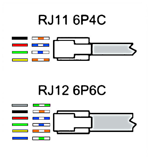
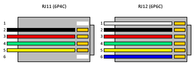
The type of wiring blue destination color code (quad cable or screw terminal) as usoc u e ca by de k ko. The rj11 and rj12 are the same size, even though they have a different number of contacts. This connector is quite often misnamed however in australia it is commonly called the rj12.
The pinouts for the 6 pin rj12 (6p6c) male connector are: It probably has an rj11, rj12 or rj45 plug. Each part ought to be placed and linked to other parts in specific way.
It also shows the motherboard and how wires are connected to the cable. Figure 1 is the wiring scheme for the plug side of an rj connector. Hi everyone is there anyone out there that might have a wiring diagram to make a connector that goes from an rj45 connector ( to plug into synscan hand controller ) to an rj12 connector ( to plug into heq5 heavy duty mount> note thanks everyone for your responses.
Pin 3 → white and orange (receive +) wire. We identified it from obedient source. Rj11 wiring diagram using cat5.
Each part ought to be placed and connected with other parts in particular way. Otherwise, the structure won’t function as it. 5 not used 6 rtn signal return common reference for logical signals.
Here are pics of the end of. Pair 1 would be the two center pins, pair 2 on the next two pins. Obviously where there are more positions the connector is necessarily larger.
Rj11 6 pin wiring diagram. Rj 12 is the line connection on the handset, rj 11 refers to the handpiece cords, and some people in their crazy mixed up world refer to the modular 4 x 4 as also an rj12. The important factor concerning the rts application of connector
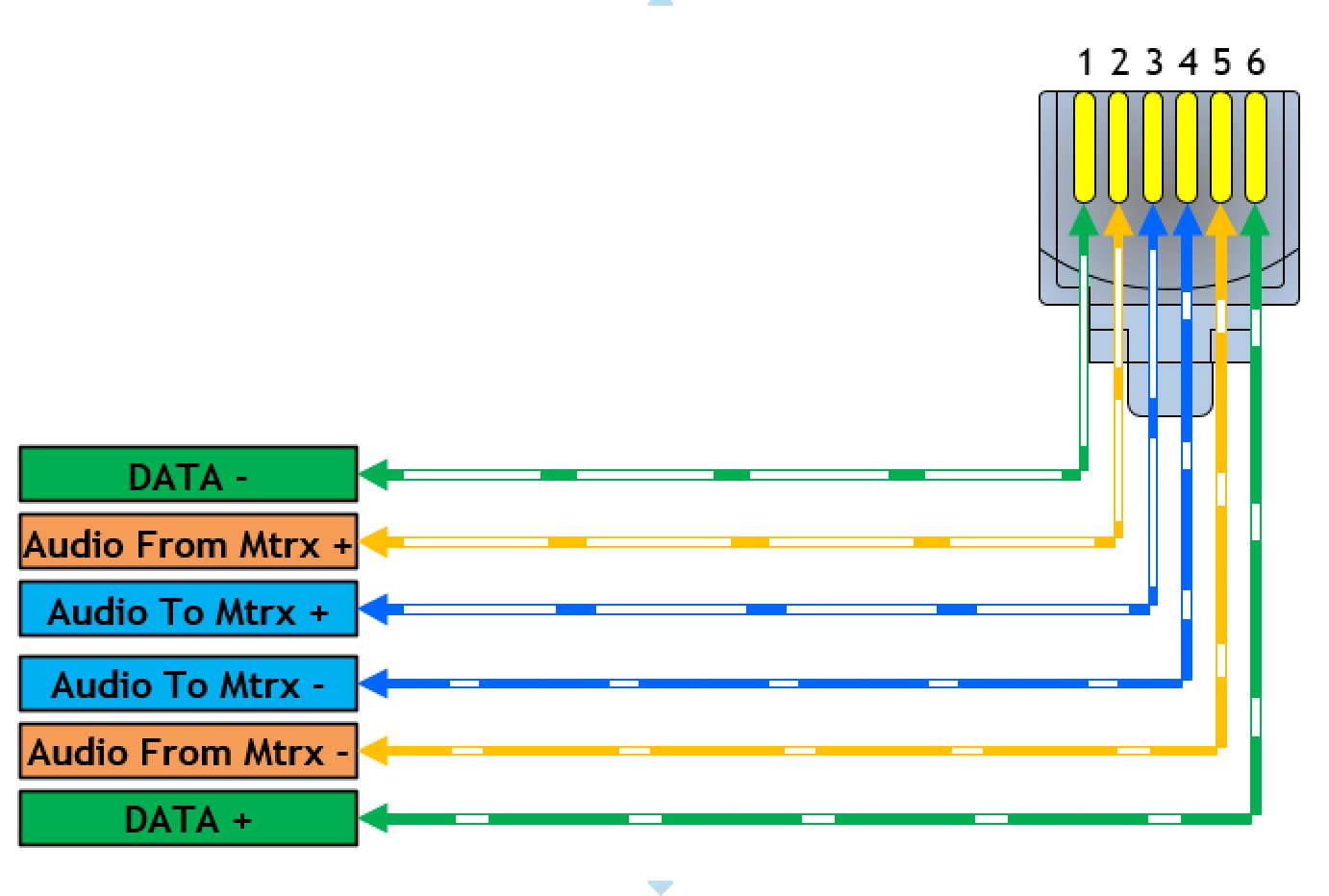
Apc rj12 serial cable pinout for apc automatic transfer switch ap7752, automatic transfer switch ap7730, automatic transfer switch ap7732, automatic transfer switch ap7721, automatic transfer switch ap7723, rack pdu ap78xx, rack pdu ap79xx, rack pdu ap86xx, rack pdu ap88xx, rack pdu ap89xx,. A registered jack (rj) is a standardized telecommunication network interface for connecting voice and data equipment to a service provided by a local exchange carrier or long distance carrier.registration interfaces were first defined in the universal service ordering code (usoc) system of the bell system in the united states for complying with the registration program for. Here are a number of highest rated rj11 6 pin wiring diagram pictures upon internet.
Pin 5 → white and blue wire. Figure 1 is the wiring scheme for the plug side of an rj 11 connector. The difference is in the number of positions available on the connector and the number of contacts actually present.
Figure 1 is the wiring scheme for the plug side of an rj connector. If you are using quad cable ie white, blue, red, black, then white and blus in the cetre and red and back on the outside of that. Rj9 connector wiring diagram bnc wiring diagram rj12 to db9 adapter wiring diagram db9 wiring diagram splitter rj11 jack wiring diagram cat5.figure 2 is the wiring scheme for the plug side of an rj connector in accordance with tb standards.
There may be instances where you may need to connect to or transpose from the old quad cable. Pin 4 → blue wire. Remember that pin 1 is on the left hand side of the rj45 connector with the clip at the rear.
White i green white bla c k white i orange i white red pair destination white / blue orange / white green / white 12344 modern color code (utp) note: Each part ought to be placed and linked to other parts in specific way. Its submitted by government in the best field.
For more information please see our telecoms wiring page. Rj12 can used to it cannot be plugged into a rj12 socket, however, a rj12 can be plugged into a rj45 socket, using a reducing sleeve. These rj11/rj12 keystone jacks provide an excellent method of bringing these jacks should be used with 24 awg solid wire, which most cat3/cat5.
We say yes this kind of rj11 6 pin wiring diagram graphic could possibly be the most trending topic next we ration it in google plus or facebook. 6 position modular jack (often called an rj11 or rj12 jack or plug.) pin configuration, utp (unshielded twisted pair cable) token ring can. Cat 5 wiring diagram australia.
The tb standard is the most commonly used. Most cable nowadays is utp (unshielded twisted pair). The wiring diagram is shown with the hook clip on the underside.
The wiring diagram is shown with the hook clip on the underside. Clipsal rj12 wiring diagram telephone rj12 wiring diagram rj12 6p4c wiring diagram rj12 socket wiring diagram rj12 wiring diagram using.
Rj12 Wiring Diagram
RJ12 Technical Characteristics instrumentic.info
Rj12 Socket Wiring Diagram

Rj12 To Rj45 Pin Wiring Diagram Complete Wiring Schemas
Rj12 To Rj45 Wiring Diagram Complete Wiring Schemas
Rj12 Wiring Diagram
Rj12 To Rj11 Wiring Diagram
Rj12 To Rj45 Pin Wiring Diagram Complete Wiring Schemas
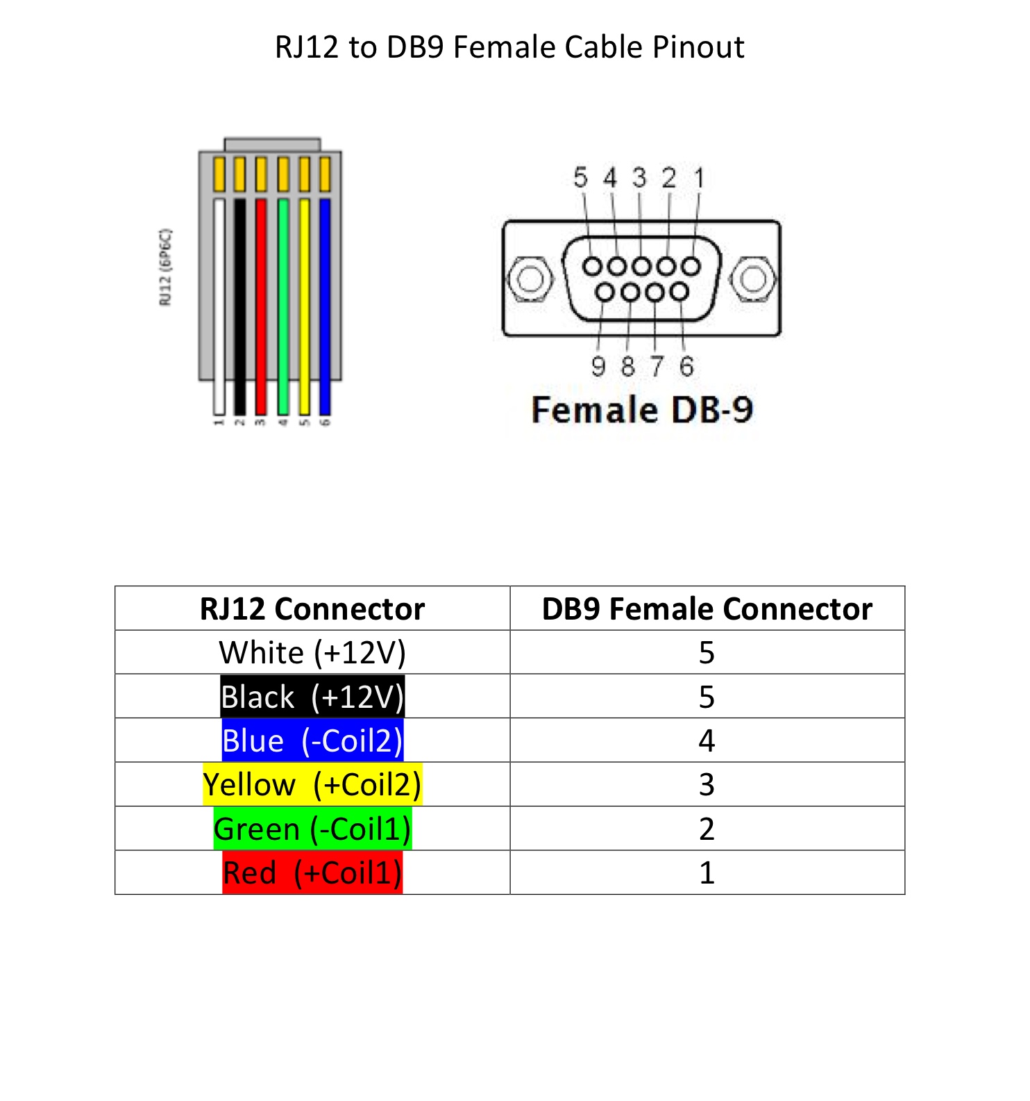
[View 42+] Db9 Connector Color Code
39 Rj45 To Rj12 Wiring Diagram Wiring Diagram Online Source
Rj12 To Rj45 Pin Wiring Diagram Complete Wiring Schemas

8Port RS485 Network Configurable Hub
Rj12 To Rj45 Wiring Diagram

Rj12 To Rj45 Wiring Diagram AOSHYWII

Rj12 Wiring Diagram
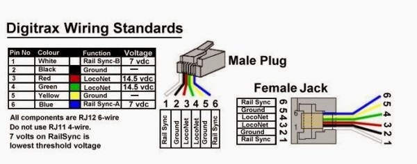
NCE DCC Cables Explained to the NCE Information Station

Rj12 Telephone Wiring Diagram Australia INHERENTLYROMANTIC

Rj12 To Rj45 Pin Wiring Diagram Complete Wiring Schemas

Rj12 To Rj45 Wiring Diagram Complete Wiring Schemas
